
Protocol is just like a common language that system uses to understand the data.
Serial communication – you are shooting a target using machine guns, where bullets reach one by one to the target.
Parallel communication- you are shooting a target using a shotgun, where no. of bullets reach at the same time.
Modes of Data Transfer in Serial Communication:
Asynchronous Data Transfer – The mode in which the bits of data are not synchronized by a clock pulse. Clock pulse is a signal used for synchronization of operation in an electronic system.
Synchronous Data Transfer – The mode in which the bits of data are synchronized by a clock pulse.
Characteristics of Serial Communication:
Baud rate is used to measure the speed of transmission. It is described as the number of bits passing in one second. For example, if the baud rate is 200 then 200 bits per Sec passed. In telephone lines, the baud rates will be 14400, 28800 and 33600.
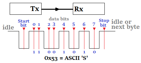
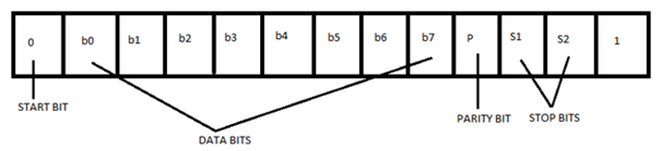
Stop Bits are used for a single packet to stop the transmission which is denoted as “T”. Some typical values are 1, 1.5 & 2 bits.
Parity Bit is the simplest form of checking the errors. There are of four kinds, i.e., even odd, marked and spaced. For example, If 011 is a number the parity bit=0, i.e., even parity and the parity=1, i.e., odd parity.
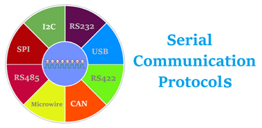
Serial Communication Protocols
Before starting with Serial Communication Protocols, Let’s break the terminology in three parts. The communication is very well known terminology which involves the exchange of information between two or more mediums. In embedded systems, the communication means the exchange of data between two microcontrollers in the form of bits. This exchange of data bits in microcontroller is done by some set of defined rules known as communication protocols. Now if the data is sent in series i.e. one after the other then the communication protocol is known as Serial Communication Protocol. More specifically, the data bits are transmitted one at a time in sequential manner over the data bus or communication channel in Serial Communication.
Types of Communication Protocols
There are different types of data transfer available in the digital electronics such as serial communication and parallel communication. Similarly the protocols are divided into two types such as Serial Communication Protocol and Parallel Communication Protocols. Examples of Parallel Communication Protocols are ISA, ATA, SCSI, PCI and IEEE-488. Similarly there are several examples of Serial Communication Protocols such as CAN, ETHERNET, I2C, SPI, RS232, USB, 1-Wire, and SATA etc.
Serial Communication Protocols
Parallel Communication Protocol
In this article, the different types of Serial Communication Protocols will be discussed. Serial communication is the most widely used approach to transfer information between data processing peripherals. Every electronics device whether it is Personal Computer (PC) or Mobile runs on serial communication. The protocol is the secure and reliable form of communication having a set of rules addressed by the source host (sender) and destination host (receiver) similar to parallel communication.
Transmission Modes in Serial Communication
As already said above that in serial communication data is sent in the form of bits i.e. binary pulses and it is well known that, binary one represents the logic HIGH and zero represents the logic LOW. There are several types of serial communication depending on the type of transmission mode and data transfer. The transmission modes are classified as Simplex, Half Duplex and Full Duplex.
a) Simplex Method:
In simplex method either of the medium i.e sender or receiver can be active at a time. So if the sender is transmitting the data then receiver can only accept and vice versa. So simplex method is one-way communication technique. The well-known examples of simplex method are Television and Radio.
b) Half Duplex Method:
In half duplex method both sender and receiver can be active but not at the same time. So if the sender is transmitting then receiver can accept but cannot send and similarly vice versa. The well-known examples of the half duplex is the internet where the user sends a request for a data and the gets it from server.
c) Full Duplex Method:
In full duplex method, both receiver and transmitter can send data to each other at the same time. The well-known example is mobile phone.
Apart from this, for appropriate data transmission, the clock plays important role and it is one of the primary source. Malfunction of the clock results in unexpected data transmission even sometimes data loss. So, the clock synchronisation becomes very important when using serial communication.
Clock Synchronization
The clock is different for serial devices and it is classified in two type viz. Synchronous Serial Interface and Asynchronous Serial Interface.
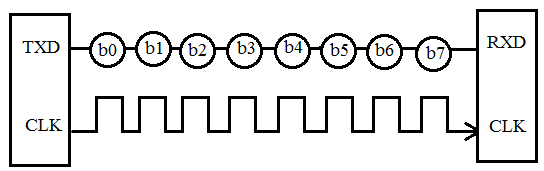
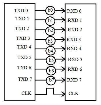
a) Synchronous Serial Interface:
It is a point-to-point connection from a master to slave. In this type of interface, all the devices use single CPU bus to share data and clock. The data transmission becomes faster with same bus to share clock and data. Also there is no mismatch in baud rate in this interface. In transmitter side, there is a shift of the data onto serial line providing the clock as a separate signal as there is no start, stop and parity bits are added to data. In receiver side, the data is being extract using the clock provided by the transmitter and converts the serial data back to the parallel form. The well-known examples are I2C and SPI.
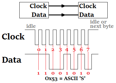
A Separate Clock Line is need in Synchronous Communication
b) Asynchronous Serial Interface:
In asynchronous Serial Interface, the external clock signal is absent. The Asynchronous Serial Interfaces can be seen in mostly in long distance applications and are a perfect fit for the stable communication. In asynchronous Serial Interface the absence of external Clock Source makes it rely on several parameters such as Data Flow Control, Error Control, Baud Rate Control, Transmission Control and Reception Control. On the transmitter side, there is a shifting of parallel data onto the serial line using its own clock. Also it adds the start, stop and parity check bits. On the receiver side, the receiver extracts the data using its own clock and convert the serial data back to the parallel form after stripping off the start, stop, and parity bits. The well-known examples are RS-232, RS-422 and RS-485.
No Separate Clock Line is need in Asynchronous Communication
Other Terms Related to Serial Communication
Apart from Clock Synchronization there are certain things to remember when transferring data serially such as Baud Rate, Data bit selection (Framing), Synchronisation and error checking. Let’s discuss these terms in brief.
Baud Rate: Baud rate is rate at which the data is transferred between the transmitter and receiver in the form of bits per second (bps). The most commonly used baud rate is 9600. But there are other selection of baud rate such as 1200, 2400, 4800, 57600, 115200. The more the baud rate will be fats the data will be transferred at a time. Also for the data communication the baud rate has to be same for both transmitter and receiver.
Framing: Framing is referred to the number of data bits to be sent from transmitter to receiver. The number of data bits differs in case of application. Most of the application uses 8 bits as the standard data bits but it can be selected as 5, 6 or 7 bits also.
Synchronisation: Synchronization Bits are important to select a chunk of data. It tells the start and end of the data bits. The transmitter will set start and stop bits to the data frame and the receiver will identify it accordingly and do the further processing.
Error Control: The error control plays an important role while serial communication as there are many factors which affects and adds the noise in the serial communication. To get rid of this error the parity bits are used where parity will check for even and odd parity. So if the data frame contains the even number of 1’s then it is known as even parity and the parity bit in the register is set to 1. Similarly if the data frame contains odd number of 1’s then it is known as odd parity and clears the odd parity bit in the register.
As described above, the serial communication protocol is divided into types i.e. Synchronous and Asynchronous. Now the both will be discuss in detail.
Synchronous Serial Protocols
The synchronous type of serial protocols such as SPI, I2C, CAN and LIN are used in different projects because it is one of the best resources for onboard peripherals. Also these are the widely used protocols in major applications.
SPI Protocol
The Serial Peripheral Interface (SPI) is a synchronous interface which allows several SPI microcontrollers to be interconnected. In SPI, separate wires are required for data and clock line. Also the clock is not included in the data stream and must be furnished as a separate signal. The SPI may be configured either as master or as a slave. The four basic SPI signals (MISO, MOSI, SCK and SS), Vcc and Ground are the part of data communication. So it needs 6 wires to send and receive data from slave or master. Theoretically, the SPI can have unlimited number of slaves. The data communication is configured in SPI registers. The SPI can deliver up to 10Mbps of speed and is ideal for high speed data communication.
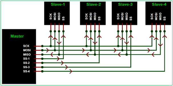
Note: Most of the microcontrollers have inbuilt support for SPI and can be directly connected SPI supported device:
I2C Serial Communication
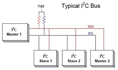
Inter integrated circuit (I2C) two-line communication between different ICs or modules where two lines are SDA (Serial Data Line) and SCL (Serial Clock Line). Both the lines must be connected to a positive supply using a pull up resistor. I2C can deliver speed up to 400Kbps and it uses 10 bit or 7 bit addressing system to target a specific device on the i2c bus so it can connect up to 1024 devices. It has limited length communication and is ideal for onboard communication. I2C networks are easy to setup since it uses only two wires and new devices can simply be connected to the two common I2C bus lines. Same like SPI, microcontroller generally have I2C pins to connect any I2C device:
USB
USB (Universal Serial Bus) is widely protocol with different versions and speeds. A maximum of 127 peripherals can be connected to a single USB host controller. USB acts as "plug and play" device. The USB are used in almost devices such as keyboards, printers, media devices, cameras, scanners and mouse. It is designed for easy installation, faster data rated, less cabling and hot swapping. It has replaced the bulkier and slower serial and parallel ports. USB uses differential signalling to reduce interference and allow high-speed transmission over a long distance.
A differential bus is built with two wire, one of represents the transmitted data and the other its complement. The idea is that the 'average' voltage on the wires does not carry any information, resulting in less interference. In USB, the devices are allowed to draw a certain amount of power without asking the host. USB uses only two wires to for data transfer and are faster than the serial and parallel interface. USB versions supports different speeds such as 1.5Mbps (USB v1.0), 480 Mbps (USB2.0), 5Gbps (USB v3.0). Length of individual USB cable can reach up to 5 meters without a hub and 40 meters with hub.
CAN
The Controller Area Network (CAN) is used in e.g. automotive to allow communication between ECUs (Engine Control Units) and sensors. The CAN protocol is robust, low-cost and message based and covers in many applications - e.g. cars, trucks, tractors, industrial robots. The CAN bus system allows for central error diagnosis and configuration across all ECUs. CAN messages are prioritized via IDs so that the highest priority IDs are non-interrupted. Each ECU contains a chip for receiving all transmitted messages, decide relevance and act accordingly - this allows easy modification and inclusion of additional nodes (e.g. CAN bus data loggers). The applications include start/stop of vehicles, collision avoidance systems. The CAN bus systems can provide speed up to 1Mbps.
Microwire
MICROWIRE is a 3Mbps [full-duplex] serial 3-wire interface essentially a subset of the SPI interface. Microwire is a serial I/O port on microcontrollers, so the Microwire bus will also be found on EEPROMs and other Peripheral chips. The 3 lines are SI (Serial Input), SO (SerialOutput) and SK(Serial Clock). The Serial Input (SI) line to the microcontroller, SO is the serial output line, and SK is the serial clock line. Data is shifted out on the falling edge of SK, and is valued on the rising edge. SI is shifted in on the rising edge of SK. An additional bus enhancement to MICROWIRE is called MICROWIRE/Plus. The main difference between the two buses seems to be that MICROWIRE/Plus architecture within the microcontroller is more complex. It supports speeds up to 3Mbps.
Asynchronous Serial Protocols
The asynchronous type of serial protocols are very essential when it comes to longer distance reliable data transfer. Asynchronous communication does not require a timing clock that is common to both devices. Each device independently listens and sends digital pulses that represent bits of data at an agreed-upon rate. Asynchronous serial communication is sometimes referred to as Transistor-Transistor Logic (TTL) serial, where the high voltage level is logic 1, and the low voltage equates to logic 0. Almost every microcontroller on the market today has at least one Universal Asynchronous Receiver-Transmitter (UART) for serial communication. The examples are RS232, RS422, RS485 etc.
RS232
The RS232 (Recommended Standard 232) is very common protocol used to connect different peripherals such as Monitors, CNCs etc. The RS232 comes in male and female connectors. The RS232 is point-to-point topology with maximum one device connected and covers distance up to 15 meters at 9600 bps. Information on the RS-232 interface is transmitted digitally by logical 0 and 1. The logical "1" (MARK) corresponds to a voltage in the range from -3 to -15 V. The logical "0" (SPACE) corresponds to a voltage in the range from +3 to +15 V. It comes in DB9 connector which has 9 pinouts such as TxD, RxD, RTS, CTS, DTR, DSR, DCD, GND.
RS422
The RS422 is similar to RS232 which allows to simultaneously send and receive messages on separate lines but uses a differential signal for this. In the RS-422 network, there can only be one transmitting device and up to 10 receiving devices. The data transfer speed in RS-422 depends on the distance and can vary from 10 kbps (1200 meters) to 10 Mbps (10 meters). The RS-422 line is 4 wires for data transmission (2 twisted wires for transmission and 2 twisted wires for receiving) and one common GND ground wire. The voltage on the data lines can be in the range from -6 V to +6 V. The logical difference between A and B is greater than +0.2 V. Logical 1 corresponds to the difference between A and B less than -0.2 V. The RS-422 standard does not define a specific type of connector, usually it can be a terminal block or a DB9 connector.
*RS485
Since RS485 uses multi-point topology, it is most used in the industries and are industry preferred protocol. RS422 can connect 32 line drivers and 32 receivers in a differential configurations but with the help of additional repeaters and signal amplifiers up to 256 devices. The RS-485 does not define a specific type of connector, but it is often a terminal block or a DB9 connector. The speed of operation also depends on the length of the line and can reach 10 Mbit / s at 10 meters. The voltage on the lines is in the range from -7 V to +12 V. There are two types of RS-485 such as half duplex mode RS-485 with 2 contacts and full duplex mode RS-485 with 4 contacts.
What is RS232?
RS232C “Recommended Standard 232C” is the recent version of Standard 25 pin whereas, RS232D which is of 22 pins. In new PC’s male D-type which is of 9 pins.
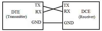
RS232 is a standard protocol used for serial communication, it is used for connecting computer and its peripheral devices to allow serial data exchange between them. As it obtains the voltage for the path used for the data exchange between the devices. It is used in serial communication up to 50 feet with the rate of 1.492kbps. As EIA defines, the RS232 is used for connecting Data Transmission Equipment (DTE) and Data Communication Equipment (DCE).
RS232 protocol
Universal Asynchronous Data Receiver &Transmitter (UART) used in connection with RS232 for transferring data between printer and computer. The microcontrollers are not able to handle such kind of voltage levels, connectors are connected between RS232 signals. These connectors are known as the DB-9 Connector as a serial port and they are of two type’s Male connector (DTE) & Female connector (DCE).
Electrical Specifications
Voltage Levels: RS232 also used as ground & 5V level. Binary 0 works with voltages up to +5V to +15Vdc. It is called as ‘ON’ or spacing (high voltage level) whereas Binary 1 works with voltages up to -5V to -15Vdc. It is called as ‘OFF’ or marking (low voltage level).
Received signal voltage level: Binary 0 works on the received signal voltages up to +3V to +13 Vdc & Binary 1 works with voltages up to -3V to -13 Vdc.
Line Impedances: The impedance of wires is up to 3 ohms to 7 ohms & the maximum cable length are 15 meters, but new maximum length in terms of capacitance per unit length.
Operation Voltage: The operation voltage will be 250v AC max.
Current Rating: The current rating will be 3 Amps max.
Dielectric withstanding voltage: 1000 VAC min.
Slew Rate: The rate of change of signal levels is termed as Slew Rate. With its slew rate is up to 30 V/microsecond and the maximum bitrate will be 20 kbps.
The ratings and specification changes with the change in equipment model.
How RS232 Works?
RS232 works on the two-way communication that exchanges data to one another. There are two devices connected to each other, (DTE) Data Transmission Equipment& (DCE) Data Communication Equipment which has the pins like TXD, RXD, and RTS& CTS. Now, from DTE source, the RTS generates the request to send the data. Then from the other side DCE, the CTS, clears the path for receiving the data. After clearing a path, it will give a signal to RTS of the DTE source to send the signal. Then the bits are transmitted from DTE to DCE. Now again from DCE source, the request can be generated by RTS and CTS of DTE sources clears the path for receiving the data and gives a signal to send the data. This is the whole process through which data transmission takes place.
| TXD | TRANSMITTER |
| RXD | RECEIVER |
| RTS | REQUEST TO SEND |
| CTS | CLEAR TO SEND |
| GND | GROUND |
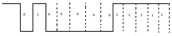
For example: The signals set to logic 1, i.e., -12V. The data transmission starts from next bit and to inform this, DTE sends start bit to DCE. The start bit is always ‘0’, i.e., +12 V & next 5 to 9 characters is data bits. If we use parity bit, then 8 bits data can be transmitted whereas if parity doesn’t use, then 9 bits are being transmitted. The stop bits are sent by the transmitter whose values are 1, 1.5 or 2 bits after the data transmission.
Mechanical Specification
For mechanical specifications, we have to study about two types of connectors that is DB-25 and DB-9. In DB-25, there are 25 pins available which are used for many of the applications, but some of the applications didn’t use the whole 25 pins. So, the 9 pin connector is made for the convenience of the devices and equipments.
Now, here we are discussing the DB-9 pin connector which is used for connection between microcontrollers and connector. These are of two types: Male Connector (DTE) & Female Connector (DCE). There are 5 pins on the top row and 4 pins in the bottom row. It is often called DE-9 or D-type connector.
Pin Structure of DB-9 Connector:
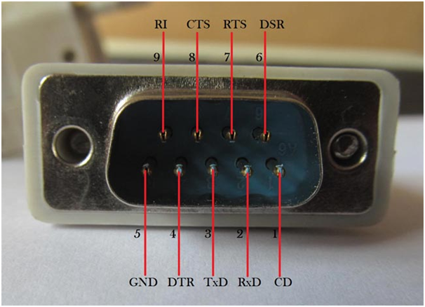
RS232 or DB9 male connector
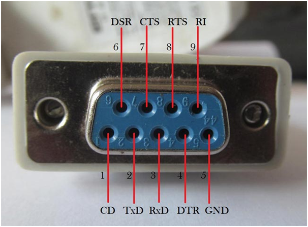
RS232 or DB9 female connector
Pin Description DB-9 Connector:
| PIN No. | Pin Name | Pin Description |
| 1 | CD (Carrier Detect) | Incoming signal from DCE |
| 2 | RD (Receive Data) | Receives incoming data from DTE |
| 3 | TD (Transmit Data) | Send outgoing data to DCE |
| 4 | DTR (Data Terminal Ready) | Outgoing handshaking signal |
| 5 | GND (Signal ground) | Common reference voltage |
| 6 | DSR (Data Set Ready) | Incoming handshaking signal |
| 7 | RTS (Request to Send) | Outgoing signal for controlling flow |
| 8 | CTS (Clear to Send) | Incoming signal for controlling flow |
| 9 | RI (Ring Indicator) | Incoming signal from DCE |
What is Handshaking?
How can a transmitter, transmits and the receiver receives data successfully. So, the Handshaking defines, for this reason.
Handshaking is the process which is used to transfer the signal from DTE to DCE to make the connection before the actual transfer of data. The messaging between transmitter & receiver can be done by handshaking.
There are 3 types of handshaking processes named as:-
a) No Handshaking:
If there is no handshaking, then DCE reads the already received data while DTE transmits the next data. All the received data stored in a memory location known as receiver’s buffer. This buffer can only store one bit so receiver must read the memory buffer before the next bit arrives. If the receiver is not able to read the stored bit in the buffer and next bit arrives then the stored bit will be lost.
As shown in below diagram, a receiver was unable to read the 4th bit till the 5th bit arrival and this result overriding of 4th bit by 5th bit and 4th bit is lost.
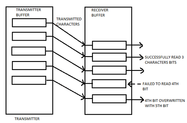
NO handshaking example
b) Hardware Handshaking:
It uses specific serial ports, i.e., RTS & CTS to control data flow.
In this process, transmitter asks the receiver that it is ready to receive data then receiver checks the buffer that it is empty, if it is empty then it will give signal to the transmitter that I am ready to receive data.
The receiver gives the signal to transmitter not to send any data while already received data cannot be read.
Its working process is same as above described in handshaking.
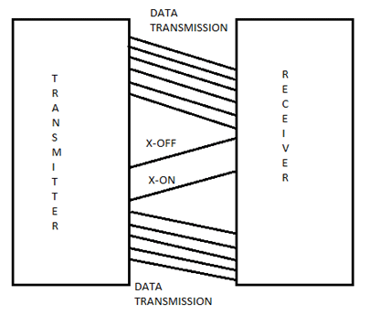
c) Software Handshaking:
In this process, there are two forms, i.e., X-ON & X-OFF. Here, ‘X’ is the transmitter.
X-ON is the part in which it resumes the data transmission.
X-OFF is the part in which it pauses the data transmission.
It is used to control the data flow and prevent loss during transmission.
Applications
RS232 serial communication is used in old generation PCs for connecting the peripheral devices like mouse, printers, modem etc.
Nowadays, RS232 is replaced by advanced USB.
It is also used in PLC machines, CNC machines, and servo controllers because it is far cheaper.
It is still used by some microcontroller boards, receipt printers, point of sale system (PoS), etc.
CAN Protocol:
The CAN protocol stands for Controller Area Network Protocol, it is kind of similar to other communication protocols like USART, SPI, I2C etc, but is very efficient than all those and widely used in vehicles like Car, Truck, Bus etc.
The ultimate duty of this CAN is to connect various ECU (Electronic Control Unit) a.k.a Nodes inside a car and allow them to communicate with each other, since these ECU’s will be present at different parts of the car. An example would be you Airbag sensor ECU, Hydraulic sensor ECU etc. A modern car could have upto 70 ECU inside them and it is the duty of the CAN protocol to enable communication between 70 ECUs without causing an overload.
But, why is CAN so popular than other protocol?
Low Cost – The CAN bus uses only two wires to communicate with all nodes, this way the number of wires required are less. So less copper and hence low cost
Centralised – CAN protocol features a Central Error diagnostics. Al the ECU will be aware of the Error if any occurs
Robust – CAN wiring uses the typical twisted pair cable which makes it robust to EMI, also the protocol is very reliable
Efficient – Every message in CAN protocol has a priority, this way more urgent messages can be addressed immediately thus making it efficient.
Flexible – Every ECU(Chip) receives all transmitted message and hence inclusion/Remove of additional Node is easy thus making it flexible.
History:
I normally don’t stress in history, but since you said it is an interview lets scratch the surface. The Idea of CAN was first coined by BOSH in 1986. Then after we works it was finally released in 1991 as two versions CAN2.0(A) which is 11-bit (CAN ID) and CAN2.0(B) which is 29-bit (CAN ID).
Then as technology progressed they released more versions like Flexible CAN released in 2012 then blah.. Blah.. blah...
It is also important know that CAN protocol is not limited to vehicles, apart from vehicles it is also used in Drones, Submarine, Prosthetic Limb and is even expected to support autonomous vehicles of the future.
CAN Connection and working rough idea:
Now let us look how the different ECU (nodes) will be connected in a CAN network. There are many ways to do this, for simplicity let’s look at the High-Speed CAN.
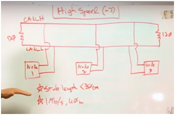
As told earlier each Node has two wires, the CAN_H and CAN_L all the information has to be exchanged by these two wires only. Every Node will have to main elements inside them they are the ECU transceiver and the ECU controller. From diagram you should be able to tell that whatever message is transmitted by any of the ECU, the message will reach all the Nodes in the network. So each message will have an unique identifier which will be read by all ECU and if that identifier’s data is required they proceed reading it else the message is neglected.
Note that in real wiring there will be more than two wires since the ground wire is required for forming twisted pair connection.
CAN protocol bit format **Important**:
To understand any protocol you should know about its bit format and what they do, for can protocol consider these are the main important 8-key parts. For understanding assume that this is for 29-bit CAN2.0 (B) . The bit format is shown in the picture below.
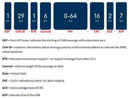
To give a brief idea the SOF and EOF are the starting and ending. After the SOF we have CAN ID which tells the node about the message and from where it is coming from. The RTR bit is used to request for a message from a Node, if this bit is sent then the nodes receiving it will understand that some data is being requested for.
Then the Control bit contains some information about the data in the message. This information includes the length of the message etc, and can be used by the receiver to check of the data was read valid. Then the actual data comes in, note that this data can only be 64-bit (8-bytes) long. Then we have the CRC which checks if the data received was correct. Finally the ACK bit is sent to indicate a successful exchange and finishes the message with EOF.
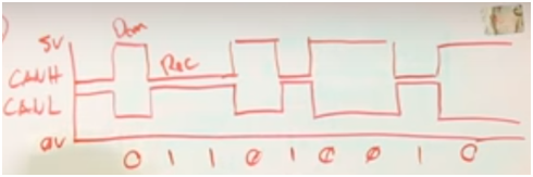
Dominant and recessive bits in CAN:
If you put a probe on the CAN_H and CAN_L lines and take it to a scope you will get something like this. This that you have note here that can operates at 5V (some case also uses 3.3V) and when the bit is low (0) the CAN_H goes to 3.5V and CAN_L goes to 1.5V this stage is called the Dominant stage and when the bit is high (1) both CAN_H and CAN_L maintain at 2.5V this stage is called the recessive stage. We obtain 2.5V because the CAN_H and CAN_L lines are terminated with 120 ohm resistors which forms a potential divider (1/2)Vcc.
Apart from this you have know few other things if you need to understand CAN. As we sae the length of data can only be 8-bytes for any data more than that we need to use other common standards like SAE J1939 which deals with the extended 29-bit identifier CAN also pave the way to OBD-II –On board diagnostics tool, which is present in almost every car today. Simply connect to this port using a OBD-II cable and you can read all the data across the CAN bus this can be used to notice standardise error, get reports and even log them using CAN data logger. There is also something called CANopen which is used in industrial automation, you also skim though it if you are interested.
Bit Stuffing in CAN:
Bit stuffing is a peculiar thing with CAN protocol so let’s discuss that too. Since CAN bus is asynchronous communication and we need to send data to all nodes, it must somehow re-sync with the bus. To do this the each nodes transceiver will try to re-sync when the signal changes from recessive to dominant.
But this will not be possible if the data bits are not changing, So they do not want more than 5 consequent bit in the same polarity so we deliberately stuff a bit after five bit so that the transceiver can re-sync. This is called bit stuffing.
Flexray: Expensive, but is faster and more reliable than CAN. Dual channel configuration allows more bandwidth so no congestion problem.
Lin: Local Interconnect network cheaper than CAN but is also slower. It is a one wore communication.
Most: MOST (Media Oriented System Transport) was introduced at the beginning of this century to simplify the integration of infotainment ECUs into the vehicle thanks to its special communication mechanisms and high data rates.
UDS: Unified Diagnostic Service. Pre-defined Diagnostic protocol.
MODBUS over Serial Line protocol
MODBUS Serial Line protocol is a Master-Slave protocol. This protocol takes place at level 2 of the OSI model.
A master-slave type system has one node (the master node) that issues explicit commands to one of the "slave" nodes and processes responses. Slave nodes will not typically transmit data without a request from the master node, and do not communicate with other slaves.
At the physical level, MODBUS over Serial Line systems may use different physical interfaces (RS485, RS232). TIA/EIA-485 (RS485) Two-Wire interface is the most common. As an add-on option, RS485 Four-Wire interface may also be implemented. A TIA/EIA-232-E (RS232) serial interface may also be used as an interface, when only short point to point communication is required.
The following figure gives a general representation of MODBUS serial communication stack compared to the 7 layers of the OSI model.
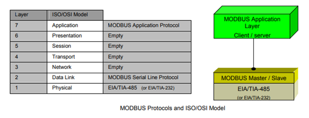
MODBUS application layer messaging protocol, positioned at level 7 of the OSI model, provides client/server communication between devices connected on buses or networks. On MODBUS serial line the client role is provided by the Master of the serial bus and the
Slaves nodes act as servers.
What is RS485?
RS485 is a serial transmission standard, a little bit like RS232, but using other electric signals. An important advantage of RS485 is that you can put several RS485 devices on the same bus. Therefore, you don't have to multiply RS485 interfaces on the host to question several devices. However, there is a small trick to do so: at each end of the bus, you must put a bus terminator. Sometimes this means that you must screw a small resistance on a terminal, or simply move a switch in the adequate position.
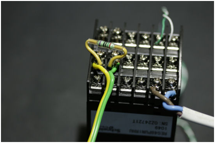
An RS485 bus is often made of just two wires and a resistor at the extremities...
RS485 and RS232 are not directly compatible: you must use the correct type of interface, or the signals won't go through. There are indeed RS232 to RS485 gateways, but they are not interesting nowadays: it's as easy to use an RS485 to USB, to Ethernet, or to GSM directly. It's cheaper and it's one less component in the system.
The main particularity when using RS485 is in the format of the exchanged data. While with RS232 many devices simply use text (ASCII) protocols, with RS485 most devices use the MODBUS protocol. You must therefore know a minimum of MODBUS to interface an RS485 device.
What is MODBUS?
MODBUS is a protocol between a host (master) and devices (slaves) to access the configuration of the devices and to read the measures. MODBUS messages correspond to relatively simple operations to read and write 16 bit words and binary registers (often called "coils"). The host systematically initiates the exchange and the "slave" device answers. The slave doesn't sent any message before the host requests it.
As there can be several devices connected in parallel on the RS485 bus, each slave device must use a unique MODBUS Slave ID on the bus. Each MODBUS request starts with the Slave ID of the intended device, each answer starts with Slave ID of the slave sending it. So, in order for the MODBUS communication to work, you must check in the device configuration its Slave ID and change it if necessary. On the way, check also communication speed and parity (same principle as RS232).
You cannot easily craft MODBUS messages "by hand", as you would have done with ASCII protocols used on RS232: each MODBUS message ends with a checksum code, computed from the full content of the message. To exchange MODBUS messages, you must therefore use:
• either a specific program provided by the device vendor, with a compatible interface;
• or a simple RS485 interface with a programming library which encodes and decodes MODBUS messages;
• or a smart RS485 interface able to encode and decode by itself the MODBUS messages, such as the Yocto-RS485.
Note as well that there are two variants of the MODBUS protocol: the MODBUS ASCII mode, where messages are exchanged as lines of hexadecimal codes, and the MODBUS RTU mode, where messages are exchanged directly as binary frames. To talk with a MODBUS device, you must imperatively use the same mode as configured in the device. All the devices which truly follow the standard support the MODBUS RTU mode. In real life, its always this latter mode which is used: MODBUS ASCII has no advantage as all the messages are in any case difficult to code by hand.
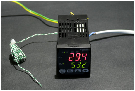
A small temperature controller with built-in PID, fuzzy logic, ... and a MODBUS interface on RS485