


KNOW US!!!
SYSTEMWORK GLOBAL is a Research & Development Organization.
We believe in mutual growth on high value and stability.
Our value proposition, combining top-quality, cost efficient and time sensitive implementation, of software solutions,
find many of our clients as a strategic long-tem partner.
Login
Search
What to expect of us?

Fair pricing
No hidden charges.
Based upon the information you provide, You will be given an upfront estimate for your project and we'll stick to it.
 Instrumentation
SYSTEMWORKS's solutions for the Automation & control industry focus on high quality software development services. Over the years, we have gained considerable expertise, working with leading players in automation, control and instrumentation.
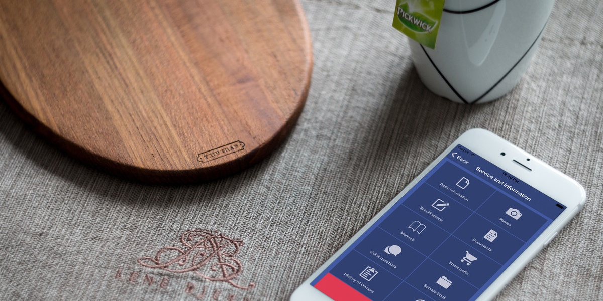
 IoT
IoT
SYSTEMWORK's hardware-enabled Data-as-a-Service solution is streamlined and secure. With this, users can collect data using any sensor, over any communications network, and integrate with any software platform.
 Custom Solutions
Developing custom software can be a complex and challenging experience. The software development process at SystemWork Global has been approached in a disciplined and organized way that avoids project failure and loss of investments in the project.
NEW PRODUCT
RUNNING PROJECT
FINISHED PROJECT
CLIENT
SYSTEMWORKS FEATURES
Application management and maintenance
Application management and maintenance is an important element towards enhancing and extending the life of the applications. SYSTEMWORK GLOBAL focuses on seamlessly maintaining and transforming your business-critical applications to meet changing business needs.
Database Administration and Support
In today’s increasingly digital world, database architecture and application infrastructure are critical components for any enterprise. Every new database that you deploy puts pressure on your IT teams to ensure it is manageable, integrated with existing databases and systems and is secure.
System Administration and Operating
SYSTEMWORK GLOBAL's aim to provide the Client with stable, efficient and fully protected environment where end users do not need to be concerned with activities connected with configuration or updating.
Package Implementation and Support
Our Packaged application portfolio includes the entire gamut of packaged application services right from package evaluation, selection, implementation, version upgrades, post-implementation support and development. Our proven methodologies and domain expertise reduce the Total Cost of Ownership of the package for your enterprise.
Network Integration
The network infrastructure forms the backbone of an organisation's business. NCS provides a broad range of network solutions and services to ensure an organisation’s network infrastructure remains robust, and scalable to support the changing business environment and manage evolving security risks.
Software Re-engineering
SYSTEMWORK GLOBAL'S Software Re-engineering Process solves all your business snags in coordination with your business process in a competent way. Re-engineering is a course of action in which an analysis of existing software system is done and due modifications are carried out to constitute a new form.
© 2018 SYSTEMWORK GLOBAL. All Rights Reserved. Designed By SYSTEMWORK GLOBAL